Thermo-Mechanical Simulations

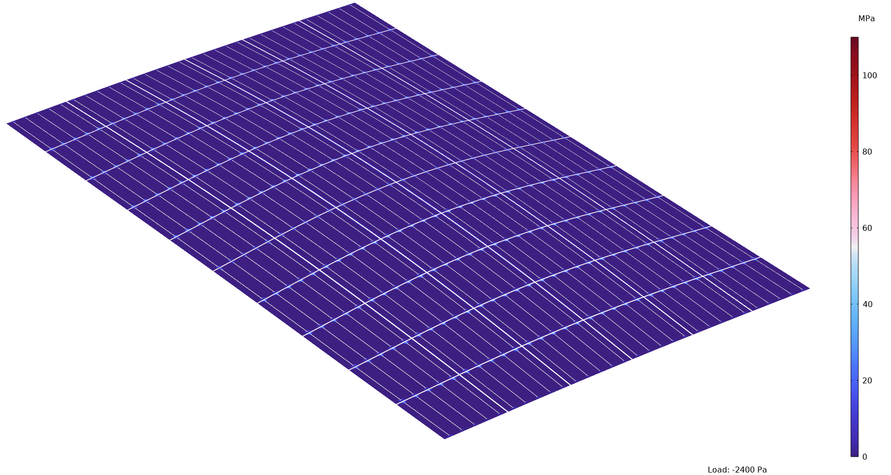
Mechanical loads are one of the main causes of PV module failure. Either due to surface loads or thermally induced mechanical loads and resulting joint failure or interconnector fatigue.

Using the finite element method, we make mechanical stresses in the PV module visible in order to minimize them. We couple structural mechanics with other physical fields, such as heat transfer for thermomechanical simulations or wind loads.

By interfacing with a CAD program and using a High Performance Computing Cluster (HPC cluster), we are able to map very complex and thus computationally expensive problems.

FEM simulation of a commercial solar module.
© Fraunhofer ISE

FEM simulation of a commercial solar module with 60 cells in mechanical load test from 2400 Pa pull to 5400 compressive load. The tensile stress in the solar cells is shown.

R&D Services for Thermo-Mechanical Simulations

In the Field of Work Module Technology we offer the following services in the field of thermo-mechanical FEM simulation:

  • Simulation of arbitrary components on a High Performance Computing Cluster (HPC cluster).
  • Virtual product development and material qualification
  • Virtual product optimization
  • Material characterization to determine the material properties, e.g. as parameter input for FEM simulations
  • Experimental validation in the accredited test laboratory TestLab PV Modules of Fraunhofer ISE


Application Examples

Thermomechanical Optimization of PV Modules

Stresses occur in a PV module during manufacturing and operation due to temperature changes and mechanical loads. These stresses can lead to fractures in the solar cells, the joints or fatigue of the cell connectors. Simulations help us understand these stresses and develop stress reduction strategies. In the manufacturing process, thermomechanical stresses occur primarily during solar cell interconnection and module lamination. Once the modules are installed in a PV power plant, mechanical and thermal forces act on the modules due to weathering.

In simulations, we reproduce the manufacturing processes as well as the load scenarios. For example, we simulate the mechanical load test and the thermal cycling test in accordance with the requirements of the IEC 61215 test standard or use measured climate data to determine the thermal stresses that occur in real operation. The FEM simulations can be used to derive how damage to the module can be avoided.

FEM simulation of load conditions of a commercial solar module with 60 cells
© Fraunhofer ISE
FEM simulation of load conditions of a commercial solar module with 60 cells.

Brief Description:

  • Target
    • Analyze the influence of different solar cell and module sizes on mechanical stability
    • Analyze the influence of different materials and their thicknesses
  • Procedure
    • Generation of a 3D FEM model of the entire module structure, including the frame
    • Simulation of the manufacturing process
    • Simulation of the mechanical load test at different temperatures
    • Evaluation based on PV module deflection and the solar cell fracture probability
  • Result

    Module optimization through the following measures to reduce the solar cell fracture probability:
    • more suitable material selection, e.g. softer encapsulation
    • Adaptation of the module design, e.g. glass-glass module
    • matched encapsulation properties and material thicknesses
    • more suitable module mounting

ECA Joints of Shingle Modules

In the shingle connection, solar cell strips are interconnected comparable to roof shingles. The absence of cell connectors results in a particularly aesthetic and homogeneous appearance of PV modules. They are also more resistant to shading. Electrically conductive adhesives (ECA) are particularly suitable for shingle connections due to their mechanical properties.

In the Field of Work Module Technology, we are investigating the mechanical behavior of such an ECA shingle joint using thermomechanical FEM simulations. Special attention is paid to the viscoelastic material behavior of the ECAs.

FEM-Simulation of an  ECA shingle joint at thermal load.
© Fraunhofer ISE
FEM-Simulation of an ECA shingle joint at thermal load.

Brief Description:

  • Target
    • Analysis of the mechanical behavior of ECA-based shingle joints
    • Optimization of the ECA shingle joints for low ECA use and increased reliability under thermal cycling
  • Procedure
    • Generation of 2D and 3D models of shingle joints
    • Determination of viscoelastic properties of ECAs
    • Simulation of the manufacturing process
    • Simulation of thermal cycling and mechanical surface load
  • Result
    • Identification of the important parameters influencing the stress within the joints
    • Optimized joint and module layout for increased reliability

Optimization of the Module Frame

The module frame has one of the highest shares in the cost and CO2 footprint of the PV module. Therefore, there is a great potential for cost savings and reduction of CO2 emissions. Using mechanical FEM simulations and other simulation tools, we analyze existing frame designs in the module technology Field of Work with regard to mechanical stability, material consumption, CO2 footprint and costs. From this, optimization potentials are identified and subjected to an analysis again. In this way, the frame design is iteratively optimized to meet individual requirements.


Biegung eines 120 Halbzellenmoduls
© Fraunhofer ISE
Simulated bending of a 120 half-cell module with optimized frame.

Brief Description:

  • Target
    • Optimization of the PV module frame in terms of mechanical stability, material consumption, CO2 footprint and costs.
  • Procedure
    • Parameterization CAD model of the frame
    • Coupling FEM model with CAD model
    • Identification of optimization potential through parameter studies
    • Complementary life cycle, cost and performance analysis
  • Result
    • Increased mechanical stability with lower material consumption and thus lower costs and CO2 footprint

Simulation of PV Noise Barriers

In the research project »PVwins«, noise barriers with integrated PV modules are being developed for use along motorways and railroad tracks. In order to ensure the best possible performance of these noise protection elements, we use FEM to simulate the acoustic behavior at different scales. Starting with the determination of the material parameters by simulating an impedance measurement using Kundt's tube, through the simulation of the sound transmission through a single PV element, to the simulation of the complete noise barrier, all relevant areas are covered.

Time propagation of sound and reflection at a PV noise barrier.

Noise barrier with PV modules
© R. Kohlhauer GmbH
Solid noise barrier with semi-transparent design and »standard« PV modules.
Schalldruckpegel
© Fraunhofer ISE
Oben: Schalldruckpegel ausgehend von einer Punktquelle, z.B. ein Auto. Der Einsatz einer PV-Lärmschutzwand (unten) verringert den Schalldruckpegel merklich.

Brief Description:

  • Target
    • • Development and optimization of PV noise protection elements
    • • Identification of suitable material classes
  • Procedure
    • Simulative determination of the required material parameters by comparison with experimentally determined measured values
    • Simulation of the sound transmission value of a PV noise protection element
    • 2D simulation of a noise protection element with integrated PV module
  • Results
    • Optimization of the arrangement of the PV modules on the noise barrier element
    • Identification of suitable material combinations to ensure better sound absorption