 Fraunhofer Institute for Solar Energy Systems ISE
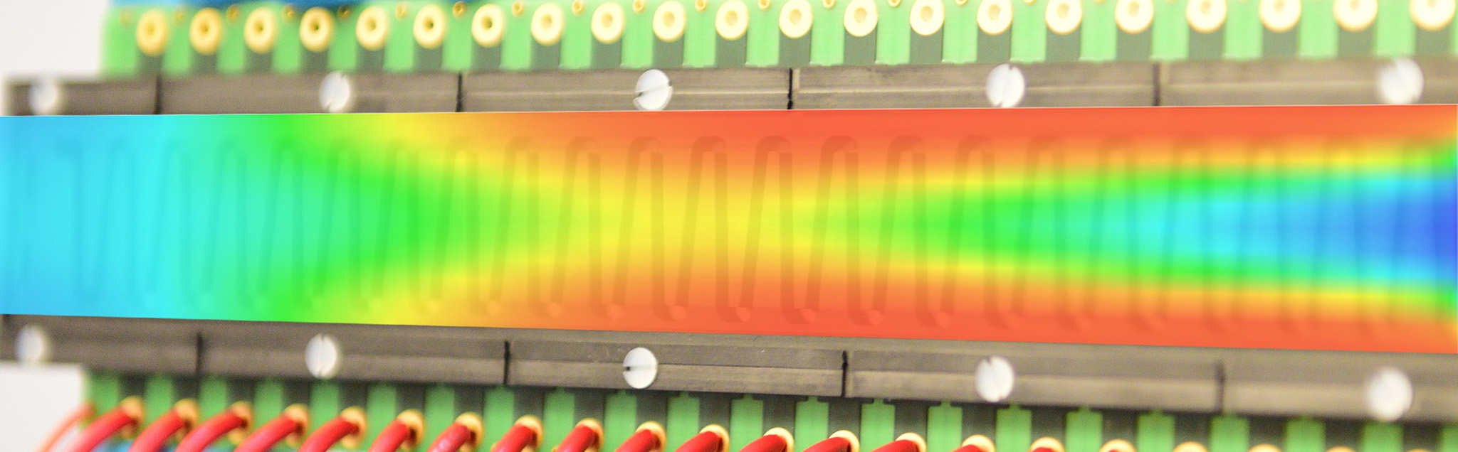
We model PEM fuel cells on all scales from the electrode structure to the fuel cell system level. Our various modeling methods shed light onto the performance and degradation in the electrode, the flow of reaction gases in the flow field and the optimization of the system behavior. We place particular emphasis on the experimental validation of our models, which provide you with detailed insights into the physical effects during fuel cell operation, with regard to cell performance and aging behavior.
We offer:
- modeling of the catalyst layer, e.g. to investigate local performance and aging as a function of operating conditions, potential or load cycles and the materials used
- flow simulation and electrochemical modeling (3D-CFD) for the design of flow fields, single cells and stacks
- system modelling to optimize system efficiency. We can investigate the effects of different operating strategies.
- use of machine learning algorithms to predict cell performance as a function of various process parameters in CCM production
Your benefits:
- Our experimentally validated models provide you with detailed insights into the physical effects during fuel cell operation with regard to performance and aging behavior.
- Our modeling helps you to determine and select optimal fuel cell materials, geometries and operating conditions.
- We can assess the effects of changes in materials, operation and design based on our many years of experience.


